
Victoria Park SLAM
Introduction
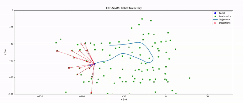
In this project, we recreate the seminal Victoria Park SLAM demonstration, in which a truck equipped with a laser range finder traverses an Australian park, collecting range and bearing measurements to nearby trees. These measurements are fused with an Ackermann-steering kinematic model of the vehicle to simultaneously localize the truck and map the positions of the tree landmarks.
For more information - Original project
Primary objectives are to:
1) Implement a SLAM algorithm (EKF-SLAM) suitable for the Victoria Park dataset.
2) Accurately estimate the vehicle’s trajectory and the spatial coordinates of the tree landmarks.
Leveraging the provided consolidated dataset—which includes steering angles, wheel-encoder velocities, and 361-beam laser scans—alongside the known vehicle geometry and motion model parameters. We filter out invalid laser returns (those beyond 75 m) and employ a standard range-bearing measurement model to associate scans with landmark hypotheses.
Methodology
EKF Prediction
In the prediction step, the filter propagates the current state estimate and its uncertainty forward in time using the odometry measurements. First, the discrete motion model computes the robot’s incremental change in position and heading from the measured forward velocity and steering angle, taking into account the vehicle geometry and the elapsed time. Next, the Jacobian of this motion model with respect to the pose is evaluated to capture how small variations in the pose affect the predicted increment. To accommodate any additional state variables such as map landmarks, the pose-only Jacobian is embedded into the full-state Jacobian. The state vector is then updated by adding the predicted increment to the previous estimate, with the heading angle wrapped back into its valid range. Finally, the covariance is propagated through the linearized motion model, the process noise is added in the pose subspace, and the resulting covariance matrix is symmetrized to maintain numerical consistency.
Landmark detection
In the obstacle extraction step, the 360 degree laser scan data is first validated to ensure a one-dimensional array of measurements and to discard any readings beyond the maximum detection range of 80m. The remaining points are paired with their corresponding bearing angles and then partitioned into segments by detecting abrupt jumps in range or angle that exceed predefined thresholds such as 1.5m for range and 10 degrees for bearing. For each segment, the start and end points are converted to Cartesian coordinates, and adjacent segments whose endpoints lie within a clustering distance threshold are merged to account for fragmented returns. Additional filtering removes segments that are too narrow in angular extent or fail to meet minimum range requirement of 1m. Finally, for each validated cluster, the midpoint distance and adjusted bearing (rotated by –90°) are computed. The algorithm returns a list of obstacle estimates, each specified by its range and bearing with respect to the robot.
Landmark association
In the data association step, each new laser measurement must be matched to an existing landmark, declared as a new obstacle or discarded if ambiguous. To do this, the filter first computes, for every known landmark, the expected range and bearing as well as the corresponding innovation covariance. It then evaluates the Mahalanobis distance between each actual measurement and every landmark prediction, populating a cost matrix. A heuristic assignment algorithm finds the lowest-cost pairing of measurements to landmarks. Measurements whose cost falls below a confidence threshold are associated with the corresponding landmark, those whose minimum cost exceeds a higher threshold are initialized as new obstacles and any measurements in between are deemed too uncertain and discarded. This association process is essential to ensure that map updates use the correct correspondence between observations and landmarks, preventing spurious updates, maintaining a consistent map of obstacles, and properly initializing newly observed obstacles.
EKF Update/Correction
In the laser measurement update step, the filter takes as input the current state, its covariance, and a set of range and bearing measurements to detected obstacles. A data association vector indicates for each measurement whether it corresponds to an existing landmark, should initialize a new landmark, or is too ambiguous and must be discarded. All measurements flagged as ambiguous are dropped at this stage, and only those associated with known landmarks or marked for initialization remain under consideration.
For each measurement associated with an existing landmark, a function is called to compute the predicted measurement and its Jacobian with respect to the full state. The predicted range and bearing are calculated from the relative position of the landmark and the robot’s pose, and the corresponding rows of the measurement Jacobian encode the sensitivity of these predictions to changes in both the robot pose and the landmark position. These individual Jacobians are stacked to form a single measurement matrix, and the innovation residual differences between actual and predicted measurements are collected into a residual vector. With the stacked measurement Jacobian and residuals in hand, the Kalman gain is computed by projecting the prior covariance through the Jacobian and adding the measurement noise covariance. Each column block of the gain matrix maps a measurement residual into a correction for the full state vector. This gain balances the trust between the prior estimate and the new sensor information according to their respective uncertainties.
The state vector is then updated by adding the gain-weighted residuals, and the robot’s heading angle is wrapped back into its valid range to avoid discontinuities. The covariance is correspondingly updated, subtracting the gain-projected measurement influence and then re-symmetrizing to maintain numerical consistency. A final adjustment ensures the covariance remains positive definite, preventing degeneracies in subsequent updates. Any measurements designated as new landmarks are then passed to a function to initialize a new landmark. This routine augments the state vector by appending the new landmark’s global coordinates, computed from the robot pose and the measured range and bearing. The covariance matrix is likewise expanded with large initial uncertainties for the new landmark entries, and the landmark count is incremented. After this step, the filter state is ready for the next prediction cycle.
To recreate, code can be found here